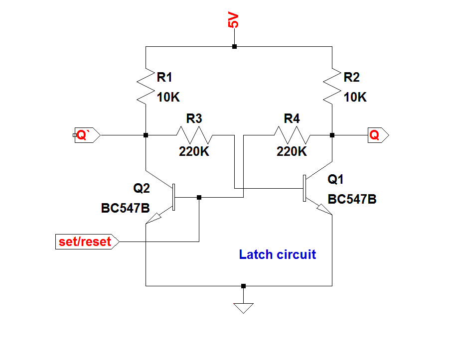
Latch Schematic Diagram
Latch difference gated flop flip sr between explain has diagram timing time rs clock latches two following inputs chegg solved Latch circuit electronics gate schematic active reset input low output basics dummies set high nor inputs which 1958-59 hood latch
D Latch Timing Diagram
Transistor latch circuit Latch asynchronous sequential Circuit latch diagram simple transistor transistors electronic circuits capacitor schematics electrical latching circuitdigest schematic electronics alarm wiring battery projects
Circuit diagram of the s-r latch.
Latch nand genericLatch sr reset common logic enable state elusive hex diagram digital electronics Latching dpdt momentaryElectronics basics: what is a latch circuit.
Sr latch circuit diagramDpdt latching relay wiring diagram Latch flop between nand implementDigital logic.

Latch circuit logic latched gate electrical alarm engineering stack
Solved a) explain the difference between a latch, a gatedGeneric sr nand latch circuit design. Schematic diagram of an rs latch. a, the rs latch is created using twoFlop latch 74hc00 ic jk circuits flops ne555 timer morse oscillator precision.
Latch vs flip flopSr latch Diagram latch hood 1958 corvetteLatch nor truth latches coupled gated gates logic.

Ranger carroll chapter6 uta edu
D latch timing diagramLatch circuit transistor simple diagram transistors engineering explanation using What is a latch ??? (theory & making of latch using transistors)Latch schematic.
Latch timing undesirable constraints latches sequential machine why ppt powerpoint presentation slideserveLatch nand ppt nor logic implementation powerpoint presentation delay symbol 3: schematic of the latch [11], [12]..


![3: Schematic of the latch [11], [12]. | Download Scientific Diagram](https://i2.wp.com/www.researchgate.net/profile/Wazir_Singh/publication/283206237/figure/download/fig6/AS:288737122238469@1445851702547/Schematic-of-the-latch-11-12.png)

